.: code PanelM_2D
calculates by panel method the integral parameters and pressure distribution on multi-element airfoil.
The user interface is implemented using FOX toolkit library.
Input data (the general data for configuration):
- FIOG = 0 - 6 - parameter defines the level of details of output calculation results.
- FNFOIL the number of elements of configuration.
- COND_GUK the length of additional panel if Zukowsky-Kutta condition is realised using the additional panel.
- N_CORR compressibility correction.
N_CORR=1 - correction of Prandtl-Glauret .
N_CORR=2 - correction of Karman-Tsien.
N_CORR=3 - correction of Laitone.
- N_Cond - the method of realisation of a condition Zhukowsky-Kutta .
N_Cond =1 - the additional panel and control point.
N_Cond =2 - equality of Cp in control points of the upper and lower panels on a trailing edge.
- ME_GEOM = 1 - the relative positioning of elements is defined by input geometry of each element.
ME_GEOM = 2 - the relative positioning of elements is defined by parameters XAX,YAX,XX,YY,DFL.
- I_BL = 1 - boundary layer calculation.
I_BL = 0 - no boundary layer calculation.
- ALPHA - angle of attack.
- MACH - Mach number.
- SWEPT - angle of swept of the infinite swept wing. Here, the geometry of infinite swept wing is specified by airfoil in normal direction to the leading edge.
- B_REF - the reference length.
- X_MZ0 X-coordinate for calculating the moment coefficient of the configuration.
- Y_MZ0 Y-coordinate for calculating the moment coefficient of the configuration.
next 5 parameters should be if I_BL = 1:
- RE mill - Reynolds number (Re_mill = 1.0 equal Re=1000000).
- ETAE - the initial value of trasformed boundary layer thickness (usually: 6-8).
- NP0_BL - the initial number steps Hj for boundary layer calculation (usually: 21-41).
- V_BL - Hj+1/Hj (usually: 1.1-1.3).
- CF_SEP = Cf*sqrt(Re), the boundary layer after separation is calculated by inverse method with specified friction coefficient
( CF_SEP=0.1 corresponds Cf=0.1/sqrt(Re)).
Input data (for each element):
- B0 - the reference length of the element.
- FNF - method of specifying the input geometry of an element.
FNF=1 -from the leading edge to the trailing edge along the upper and lower surfaces
FNF=2 -from the trailing edge along the upper surface to the leading edge, along the lower surface to the trailing edge.
FNF=3 -from the trailing edge along the lower surface to the leading edge, along the upper surface to the trailing edge.
- FNP - the number of nodes of the input geometry
- FNM - the number of panels on the element (even, <590, summa of the panels of the multi-element configuration <1180)
- FNROT - to align the element chord with the X axis or not?
FNROT=0 - no align.
FNROT=1 - to align.
- FNSM - Parameter of smoothing
FNSM=0 - no smoothing.
FNSM=1 - smoothing.
- FNLE - the sequence number of the leading edge node in input geometry of the element
- SCALE - the scale of the input geometry of the element.
- XAX X-coordinate of the rotation axis in the coordinate system of the element.
- YAX Y-coordinate of the rotation axis in the coordinate system of the element.
- XX X-coordinate of the rotation axis in the coordinate system of the main (the first in the input file) element.
- YY Y-coordinate of the rotation axis in the coordinate system of the main (the first in the input file) element.
- DFL - the angle of deflection of the element.
- X_MZ X-coordinate for calculating the moment of the element.
- Y_MZ Y-coordinate for calculating the moment of the element.
The input file FN.dat have to contain these data.
|
.: Panel: Multi Element Airfoil Calculation
This panel contains the graphic window with the view of the multielemeht aerofoil
and the pressure distribution on each element.
Each time the [SAVE RESULT] button is pressed, a new file InputFile_i.sum,
(i-sequence number) is created with the current calculation result .
|
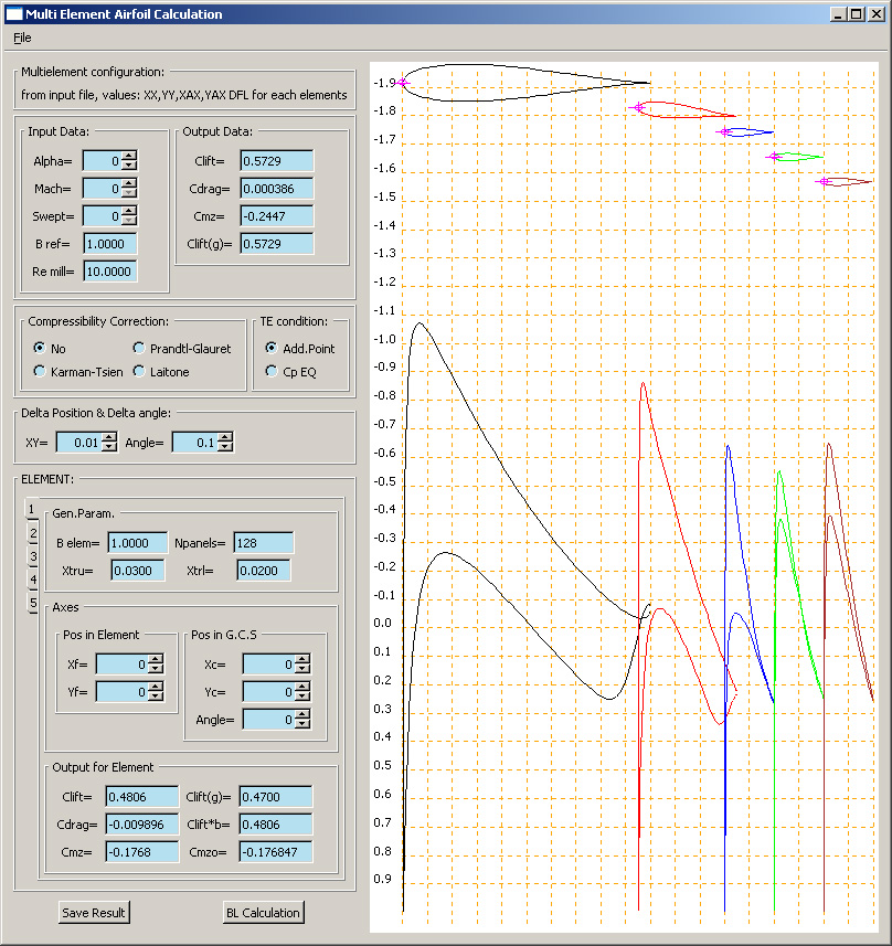 |
.: general input data:
| Alpha | angle of attack |
| Mach | Mach number |
| Swept | angle of swept of the infinite swept wing. |
| B ref | the reference length |
|
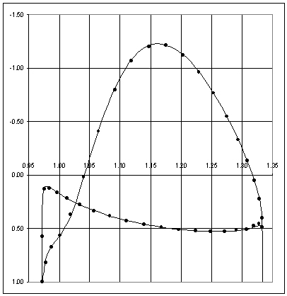
.: calculation results:
| Clift | total lift coefficientи |
| Cdrag | total drag coefficient |
| Cmz | total moment coefficient |
| Clift(g) | total lift coefficient (summa gamma) |
|
.: compressibility correction:
| No | no correction |
| Prandtl-Glauret | Prandtl-Glauret correction |
| Karman-Tsien | Karman-Tsien correction |
| Laitone | Laitone correction |
|
.: Zhukowsky-Kutta condition:
| Add.Point | additional panel and control point |
| Cp EQ | equality of Cp in the control points of the upper and lower panels at the trailing edge |
|
.: Increment:
| XY | Increment for axis position |
| Angle | Increment for angle position |
|
.: Parameters for each elements:
| main: |
| B elem | the reference length of element |
| Npanels | number of panels on the element |
|
| Axis position: |
| Xf | X-coordinate of the rotation axis in the coordinate system of the element. |
| Yf | Y-coordinate of the rotation axis in the coordinate system of the element. |
| Xc | X-coordinate of the rotation axis in the coordinate system of the main (the first in the input file) element. |
| Yc | Y-coordinate of the rotation axis in the coordinate system of the main (the first in the input file) element |
| Angle | angle of deflection of the element |
|
| integral calculation results: |
| Clift | the lift coefficient of the element related to reference length of element |
| Cdrag | the drag coefficient of the element related to reference length of element |
| Cmz | the momentum coefficient of the element related to reference length of element |
| Clift(g) | the lift coefficient of the element (summa gamma) |
| Clift*b | the lift coefficient of the element |
| Cmzo | coefficient of the element's moment relative to the leading edge of the main (the first in the input file) element |
|
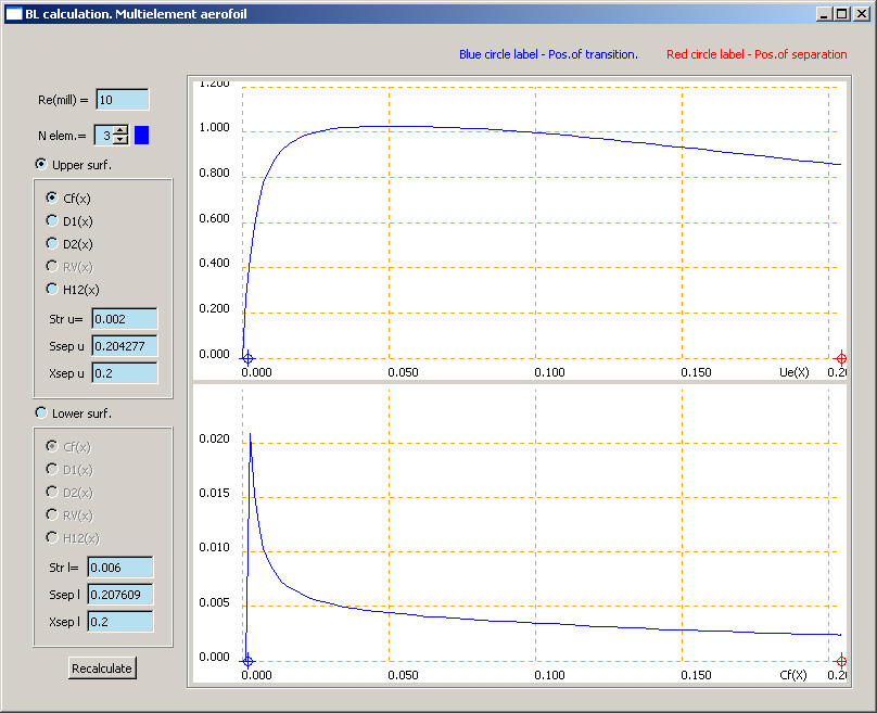
If you press the button [BL Calculation] on the panel Multi Element Airfoil Calculation
the boundary layer is calculated on the upper and lower surfaces of each element.
Then you will see the panel BL calculation. Multielement aerofoil .
|