The page is under construction !!!

.: code InfSWing

Calculates the distributed and integral characteristics of subsonic or transonic flow around an infinite swept wing at given Mach number, angle of attack, and sweep angle. The flow is calculated by numerical integration of the conservative form of the full potential equation with correction for non-isentropic conditions in the vicinity of shocks. The resulting system of non-linear equations is solved using a combination of the Newton-Raphson method and GMRES(R) method preconditioned using incomplete LU factorization. The calculations are performed on a C-type grid created using a simple algebraic generator.

The inverse problem works for three modes:

  1. Design both upper and lower surfaces.
  2. Design upper surface and preserve airfoil thickness distribution.
  3. Design upper surface and preserve maximum airfoil thickness.

The graphical user interface is implemented using Fox ToolKit library.

.: User Guide for InfSWing code

.: panel InfSWing Calculation:

From the menu [File] -> [Open] select an airfoil geometry file.

after selecting the source file, the [Grid] tab will be available

.: tab Grid:

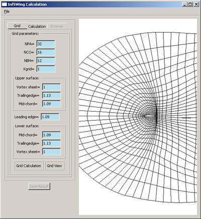
NPA Number of nodes along the airfoil surface
NCO Number of nodes in the outer direction
NBH Number of nodes along the wake sheet
Kgrid Grid refinement levels (must be 1,2 or 4)
Vortex sheet Outward grid spacing growth rate off wake sheet
Mid-chord Outward grid spacing growth rate off mid-chord
Leading edge Outward grid spacing growth rate off leading edge

Press [Grid Calculation] to generate the grid.

Press [Grid View] to show the generated grid.

.: tab Calculation:

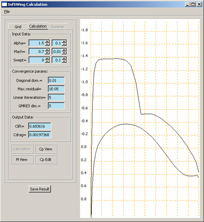
Alpha Angle of attack
Mach Mach number
Swept Sweep angle
Diagonal dom. Diagonal dominance
Max. residual Maximum residual
Linear iterations Number of linear iterations
GMRES dim. Number of GMRES dimensions before restart
Clift Lift coefficient
CdragDrag coefficient (integral Cp)

Press [Calculation] to start the calculation.

Press [Cp View ] to show Cp distribution.

Press [M View ] to show Mach number distribution.

Press [Cp Edit] to edit target Cp distribution.

Left mouse button translation
Left mouse button + Shift zoom

.: tab Cp Edit:

Cyt Lift coefficient (initial Cp)
Cyd Lift coefficient (target Cp)
Nspl Number of spline nodes on the modifiable interval
U1 U2 Modifiable interval on the upper surface
L1 L2 Modifiable interval on the lower surface
select a node to edit by left-clicking it,
the node is highlighted in red
drag the selected node up or down on the plot to a desired position

Press [Cp design save] to saves the current target Cp distribution

.: tab Inverse:

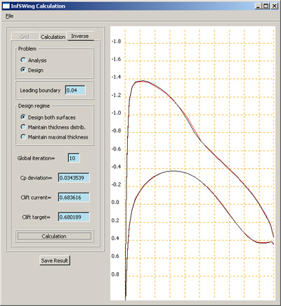
Leading boundary Fixed geometry part near leading edge (value of 0.04 specifies 4% of chord length)
Global iteration Number of global iterations
Cp deviation computed vs target Cp tolerance
Clift current lift coefficient (current)
Clift target lift coefficient (target)
Inverse problem mode:
Design both surfaces Design both upper and lower surfaces
Maintain thickness distribution Design the upper surface and preserve airfoil thickness distribution
Maintain maximum thickness Design upper surface and preserve maximum airfoil thickness

Black line - initial Cp distribution

Red line - target Cp distribution

Add a global solution iteration by pressing [Calculation]


Every global iteration consists of the following 3 steps:

  1. The inverse design problem is solved to obtain new velocity gradients along the airfoil surface.
  2. Airfoil geometry is modified according to the computed gradients.
  3. The flow solution is recalculated using the modified geometry.

.: Example of the input file:

RAE-2822
MACH ALFA HEE
0.72 1.5 0.00000
BETA ERM CLU
.01 1.E-5 0.04
FNPA FNCO FNBH FKGR
16. 8. 12. 2.
FNLN FMGT FICY FIDG
5. 3. 0. 0.
FNF FNP
0. 33.
XU YU
1.000000 0.000935
0.986047 0.004450
0.953994 0.009902
0.905037 0.019071
0.840999 0.031107
0.764266 0.043588
0.677698 0.055109
0.584520 0.064556
0.488203 0.071295
0.392337 0.074861
0.300493 0.074846
0.216094 0.071192
0.142284 0.064244
0.081813 0.054361
0.036934 0.041518
0.009320 0.023419
0.000000-0.000000
0.009320-0.021822
0.036934-0.039221
0.081813-0.052897
0.142284-0.063740
0.216094-0.071305
0.300493-0.074654
0.392337-0.073152
0.488203-0.066250
0.584520-0.053968
0.677698-0.037751
0.764266-0.021036
0.840999-0.008324
0.905037-0.001757
0.953994 0.000043
0.986047-0.000044
1.000000-0.000935
G01G04G06G07G08G10G13
1.00 1.13 1.09 1.09 1.09 1.13 1.00

.: Description of the input file:

line 1
Title
line 3
MACH Mach number
ALFA Angle of attack
HEE Sweep angle
line 5
BETA Diagonal dominance
ERM Maximum residual
CLU Fixed geometry part near leading edge (value of 0.04 specifies 4% of chord length)
line 7
FNPA Number of nodes along the airofoil surface
FNCO Number of nodes in the outer direction
FNBH Number of nodes along the wake sheet
FKGR Grid refinement levels (must be 1,2 or 4)
line 9
FNLN Number of linear iterations
FMGT Number of GMRES dimensions before restart
FICY 1 - Target Сp correction to maintain lift coefficient
0 - No correction
FIDG Design mode
0 Design both upper and lower surfaces
1 Design upper surface and preserve airfoil thickness distribution
2 Design upper surface and preserve maximum airfoil thickness
line 11
FNF Geometry description method
0 XT YU - upper trailing edge
X Y - upper surface
...
X0 Y0 - leading edge
X Y - lower surface
...
XT YL - lower trailing edge
1 X0 Y0 Y0 - leading edge
X YU YL - upper and lower surfaces
...
XT YU YL - trailing edge
FNSP Number of lines in geometry description
line 13
XU YU
...
XL YL
...
If FNF = 0
X YU YL
...
If FNF = 1
line NSP+12
G01 Upward grid spacing growth rate off wake sheet
G04 Upward grid spacing growth rate off trailing edge
G06 Upward grid spacing growth rate off mid-chord
G07 Outward grid spacing growth rate off leading edge
G08 Downward grid spacing growth rate off mid-chord
G10 Downward grid spacing growth rate off trailing edge
G13 Downward grid spacing growth rate off wake sheet
Downloads: